How to use Bluetooth with Arduino

In this post, we will concentrate on how to use a Bluetooth module with the Arduino Uno. Bluetooth as we know is an electronic data exchange protocol over short distances. There are many different types of Bluetooth chips available in the market such as:
  • HC-04, HC-05 and HC-06
  • RN-41 and RN-42
  • AUBTM series chips

The multitude of chips are designed to fulfill different types of objectives. For example, range or the maximum distance over which communication is possible. In this post, we will use the HC-05 bluetooth chip which is a Class 2 bluetooth device. All Class 2 bluetooth devices should have an approximate range of 30 feet. In order to give you an idea of how you may put the bluetooth module to use, we will see how to blink a LED remotely by sending commands from a Windows Phone. The Arduino sketch used in this example is written in such a way that it will receive a number between 1 and 5, then depending on the number received from the phone, it will blink the LED that many number of times.

To start with let us inspect the HC-05 bluetooth chipset and try to understand the pins that are needed for making a connection with the Arduino Uno.

HC-05 Bluetooth
Figure 1 - HC-05 Bluetooth

There are 6 pins provided with the chip. Out of the 6 pins we will be using only 4 pins for the bare minimum interfacing.
  • Rx Pin (HC-05): This pin will be connected to Arduino Uno's Tx pin. However, we will shift Arduino's 5V to 3.3V using a votage divider. That is because the HC-05 module's Rx pin uses 3.3V.
  • Tx Pin (HC-05): Connect this pin to Arduino's Rx pin directly. Although HC-05's Tx pin works at 3.3V, it would still be sufficient for Arduino's RX pin which operates at 5V.
  • Gnd Pin (HC-05): This pin should be connected to Arduino's Gnd pin directly.
  • +5V (HC-05): This pin should be connected to Arduino's 5V pin. The current drawn by HC-05 should be less than 50mA, hence it should get the required current from Arduino's 5V pin.

For using the HC-05 with Arduino Uno, the first thing that we will have to do is to connect the chip with the Arduino Uno as explained above. You may follow the schematic diagram shown below for easy reference.

Using Bluetooth with Arduino
Figure 2 - Using Bluetooth with Arduino

Big Caution: DO NOT connect the Jumper wires to Arduino's Tx and Rx pins while loading the C sketch, to avoid loading the program to the Bluetooth device.

Good Practice: DO NOT connect anything to the Arduino while loading a program.

Once nothing is connected to the Arduino board, except the cable to your computer, load the following C sketch into your Arduino Uno for interfacing the LED with the Bluetooth module, as shown in the picture above.


Now connect the HC-05 module to the Arduino board and power on the Arduino board by connecting to your computer USB port.

On the other end, launch BT Terminal on your windows phone.
Connect to your HC-05.
In the Communication screen, send any number between 1 and 5 (as per your choice), as shown below.
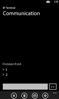
Sending commands to HC-05 from Windows Phone
Figure 3 - Sending commands to HC-05 from Windows Phone


As soon as you send a number the on-board  LED on Arduino's Pin 13 will blink that many number of times.

That's it! You have established a basic bluetooth connected project.

Cheers!
KBRC

ThingSpeak Library with Arduino UNO

Installing the ESP8266 Library for the Arduino IDE

          ESP8266 works with the Arduino Uno by utilizing the ESP8266 library. In this section, we will see how to install the ThingSpeak API for ESP8266 with Arduino Uno. This is a pre-requisite of installing the ThingSpeak library, before we can log data to the cloud. You will need this library in order to include the ThingSpeak.h file in the sketch below.
  • Launch the Arduino IDE.
  • Navigate to Sketch > Include Library > Manage Libraries...
  • The Library Manager window will pop up.
  • In the Library Manager window, search for ThingSpeak and install the required library. The library that I choose to install is shown below.

Installing the ThingSpeak API for the Arduino IDE

          In this section, we will see how to install the ThingSpeak API for ESP8266 with Arduino Uno. This is a pre-requisite of installing the ThingSpeak library, before we can log data to the cloud. You will need this library in order to include the ThingSpeak.h file in the sketch below.
  • Launch the Arduino IDE.
  • Navigate to Sketch > Include Library > Manage Libraries...
  • The Library Manager window will pop up.
  • In the Library Manager window, search for ThingSpeak and install the required library. The library that I choose to install is shown below.
Figure 3 - ThingSpeak API for ESP8266 with Arduino Uno

Post Data to ThingSpeak - Bad Request Problem Solved

In this post we will see the series of AT Commands that you may use from any serial terminal in order to successfully post data to ThingSpeak IoT Cloud.  Many people have reported of getting a Bad Request error returned when they tried to post data to the ThingSpeak server. It was indeed very tricky to figure this out a way to fix the Bad Request problem. Hence I am sharing this information as it was very troublesome to find all the required information in one place on the Internet.

Pre-Requisites

This post assumes that you already have an ESP8266 and a FTDI FT232RL USB to TTL Converter connected properly. You can refer for full connection details here.

The Data Logging Session

For sending data to ThingSpeak use the following series of AT commands from the Arduino Serial Monitor or from any other terminal of your choice. Set the Serial baud rate at 11500 and Both NL & CR. Then execute the following AT Commands.

AT

AT+CWLAP

AT+CWJAP="your-wifi-ssid","your-password"

AT+CIPSTART="TCP","184.106.153.149",80

AT+CIPSEND=60

GET /update?key=<your-channel-api-write-key>&field1=56\r\n        (from my Arduino IDE's Serial Monitor, I had to send this line 2 times...I don't know why yet)

AT+CWQAP

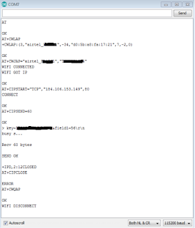
That is all! This should work fine. My Serial window snip is shown below for reference.

Post Data to ThingSpeak - Bad Request Problem Solved


Summary - The Trick

In the series of AT commands above notice the line "AT+CIPSEND=60", the number 60 here means the number of text characters (technically bytes) that will be sent in the request. It is referred to as the Data Length. Read below and see how to manipulate this Data Length setting in order to solve the Bad Request problem.

The request text is in the line "GET /update?key=<your-channel-api-write-key>&field1=56\r\n". In my case, the number of characters in this request text was 46 (including the last \r\n characters, you will have to count them as well). However, I specified 60 as the Data Length. This is the trick. You will have to mention the Data Length a little bit higher than the actual size of the Request Text length.

Cheers!
KBRC

If you liked this post, then your encouragement by performing a G+ and a share is most welcome and highly appreciated!

How to configure ESP8266 baud rate?

The ESP8266 baud rate must be changed to 9600 before connecting the ESP8266 with the Arduino Uno. The baud rate of your ESP8266 should be set to 9600, so that you can communicate with it via your Arduino IDE's Serial Monitor and also via the Software Serial while issuing AT commands for connecting from the C program to the internet.

By the way, setting up the FTDI FT232RL USB to TTL Converter is a separate topic altogether. You will have to set up the USB to TTL converter before you can use it to configure the ESP8266. You can read my detailed post of setting up the FTDI FT232RL USB to TTL Converter.

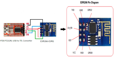
For changing the baud rate of the ESP8266 connect the chip with the USB to TTL converter as shown below. Also note that there is another way of using your Arduino Uno board to configure the ESP8266 chip, instead of the USB to TTL converter - in which case you do not need to use the USB to TTL FTDI chip - will write about it in a later post.

Caution: The FTDI FT232RL USB to TTL Converter I used had a jumper to select voltage level between 3.3V and 5V. Before connecting, I had switched the jumper to the 3.3V level. If your USB to TTL converter does not come with 3.3V, then you must use the voltage divider technique to obtain 3.3V on the Vcc and Tx pins.


Configure ESP8266 Baud Rate
Figure 1 - Configure ESP8266 baud rate using USB to TTL converter

Connect the ESP8266 to your PC, via the USB to TTL converter as explained below.
  • PC USB A --> USB to TTL FTDI
  • USB-to-TTL FTDI TX --> ESP8266 RXD (via voltage divider, if 3.3V mode not available)
  • USB-to-TTL FTDI RX --> ESP8266 TX
  • USB-to-TTL FTDI GND --> ESP8266 GND
  • USB-to-TTL FTDI VCC --> ESP8266 VCC and CH_PD (via voltage divider, if 3.3V mode not available)
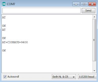
Next in order to configure ESP8266 chip's baud rate, fire up the Arduino IDE and browse to the Serial Monitor. In the serial monitor, you will have to perform some trial and error to find out the existing baud rate of your ESP8266 chip. Set the line ending to "Both NL & CR". Then start with the highest rate of 115200, then type the command AT in the Serial Monitor and send it to the ESP8266 chip. If the selected baud rate matches the you will see OK displayed as a reply in the Serial Monitor window. Repeat this process of changing the baud rate from the Serial Monitor and pinging the ESP8266 chip with the AT command, until you receive OK as a reply. In my case (shown below) the factory set baud rate was 115200.

Using ESP8266 with Arduino Uno
Figure 2 - Finding Factory Set Baud Rate of ESP8266

If the baud rate matches with 9600, then no further action is required and you may proceed with setting up the ESP8266 with the Arduino Uno. If the matching baud rate is something other than 9600, then you will have to change the baud rate of your ESP8266 chip by issuing the following AT command (AT+CIOBAUD=9600) in the Serial Monitor window.

Using ESP8266 with Arduino Uno
Figure 3 - Change Baud Rate of ESP8266

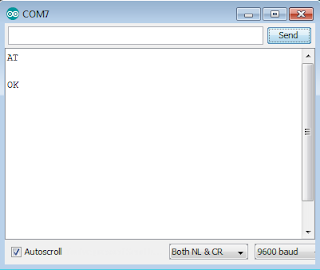
This is how you configure the baud rate of your ESP8266 chip! Just to be sure that the baud rate was indeed changed, issue the command AT in the Arduino Serial window. You should receive OK as a reply if everything went successfully so far. Otherwise repeat the AT command to change the baud rate.

How to setup the FTDI FT232RL USB to TTL Converter?

I was working on an Arduino and ESP8266 project, during that time I had to setup the FTDI FT232RL USB to TTL converter on my laptop. Normally, you will need the FTDI FT232RL USB to TTL converter for talking to other chips from your computer and you can also use it to push programs into other micro-controller boards.

Setup FTDI FT232RL USB to TTL Converter

Given below is the first-hand account of my experience setting up this device on my laptop. Setting up the FTDI FT232RL USB to TTL converter chip is a 2 step process:
  • Step-1: FT232R USB UART Installation
  • Step-2: USB Serial Port Installation

Pre-Requisites

The pre-requisite step, for setting up the FTDI FT232RL USB to TTL Converter. was to download and install the correct software driver for the FTDI FT232RL USB to TTL converter. The driver is available on the FTDIChip website. You may browse to the driver download link here and download a compatible (for your operating system) version of the driver.

My laptop was powered by Windows 7’s 64-bit version. I used the x86 (32-bit), v2.12.18 driver for Windows. A snapshot taken from the FTDIChip website tabulating various drivers available for the FTDI FT232RL USB to TTL converter is shown below.

Setup FTDI FT232RL USB to TTL Converter


Step-1: FT232R USB UART Installation

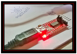
The first step, for setting up the FTDI FT232RL USB to TTL Converter, is to connect the FTDI FT232RL USB to TTL converter to my laptop/PC using a USB A (on the laptop/PC side) to USB Mini B (on the FTDI FT232RL USB to TTL converter side) cable.

After making the basic cable connection, for setting up the FTDI FT232RL USB to TTL Converter,  you will notice that the LED on the FTDI FT232RL USB to TTL converter starts glowing.

Setup FTDI FT232RL USB to TTL Converter

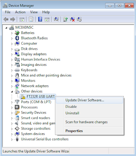
Now from your laptop/PC, navigate to Control Panel > Device Manager. In the Device Manager window you will notice a node named “Other devices”, under that there will be a device listed as “FT232R USB UART” – however, the device will have a yellow icon against it indicating that it is not yet ready to be used.

In order to install the downloaded device driver, simply right-click on the device listing, and choose the “Update Driver Software…” option from the context menu, as shown below.

Setup FTDI FT232RL USB to TTL Converter

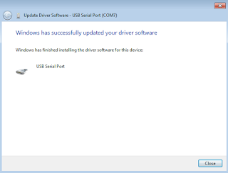
Thereafter, follow the on-screen instructions, in order to install the FTDI FT232RL USB to TTL Converter. During the installation, remember to point to just the base (top level/starting) folder location (pointing to an exact file is not required) where you had downloaded and unzipped the driver files.

After the installation, you will receive the following message that the device installation was successful.

Setup FTDI FT232RL USB to TTL Converter

However, at the same time you will also notice that there is a pop up notification in the System Tray saying that the installation was not successful. Do not get confused by this behavior, as I already told you that setting up the FTDI FT232RL USB to TTL converter chip is a two step process. As a next step, we will now proceed to install the port.


Step-2: USB Serial Port Installation


Once again, for setting up the FTDI FT232RL USB to TTL Converter, browse to the Device Manager and navigate to the “Other devices” node. You will notice that the name of the device has changed to “USB Serial Port” this time. Right-click on the “USB Serial Port” and just like in Step-1, choose the “Update Driver Software” option from the context menu.

Setup FTDI FT232RL USB to TTL Converter

This time also provide the same base folder path, just like you did in Step-1 for setting up the FTDI FT232RL USB to TTL Converter. The USB Port driver is also in that same location. Follow the on-screen instructions and complete the installation. After the installation completes successfully, you will be greeted with the following screen.

Setup FTDI FT232RL USB to TTL Converter

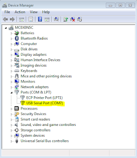
Go back to the Device Manager window and find the newly installed FTDI FT232RL USB to TTL converter, as shown below. In my case, it was listed as “USB Serial Port (COM7)”.

Setup FTDI FT232RL USB to TTL Converter


Conclusion

You are all set to use your FTDI FT232RL USB to TTL converter to talk to other chipsets, via any serial monitor.

Fetching Data From ThingSpeak IoT Cloud

In this post we will see how to fetch data from ThingSpeak (an IoT Cloud plarform). The data can be fetched from any client device: A laptop, mobile or a micro-controller.

We will use a JQuery based web page on a laptop, to fetch the data logged into ThingSpeak. You may visit my other post on setting up a device channel in ThingSpeak for a tutorial on the pre-requisites.

The HTML/JQuery Code

The JQuery based web page has been coded in such a way that it will fetch the last logged data row every 10 seconds. The re-usable code has been provided below.


Steps to re-use the above code

Follow these steps to re-use the above code.
  1. Download the JQuery library. I have used "jquery-1.12.1.min.js". You are free to chose, but if you do, then make sure you update the HTML appropriately.
  2. Copy the code
  3. Create an HTML file in the same directory as the JQuery library
  4. Paste the code in the HTML file
  5. Make sure you change the channel ID in the GetData() function to fetch data from your device channel. However, I have left mine "as is" in the above code, so that it works out of the box for you.
  6. Save and close the HTML file
  7. Open the HTML file in a browser
  8. Every 10 seconds it should fetch data from ThingSpeak and display it on the screen

Running the HTML/JQuery App

Follow these steps outlined below.
  1. Just right click and open with a browser.
  2. This is what I see when I open the HTML file.
Fetching Data From ThingSpeak IoT Cloud

What Next?

Well, this is how you can fetch the logged data from your remote sensors or edge devices via an IoT Cloud such as ThingSpeak. Of course you may perform a lot of things hereafter: predictive analytics, machine learning and so on...

Cheers,
KBRC


Setting up a Device Channel in ThingSpeak IoT Cloud

In this post we will see the process of Setting up a device channel in the IoT Cloud platform ThingSpeak.

Step-1: The first step is to create an account. The good part is that ThingSpeak does not require a Credit card (like AWS/Azure) for signing up. You may sign up here.

Step-2: After signing up on ThingSpeak, login here.

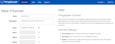
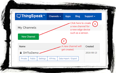
Step-3: Create a new ThingSpeak channel by clicking on the "New Channel" button shown below.

Create New ThingSpeak Channel

Step-4: In the new channel creation screen, fill out the details of the device from which data will be received.

Create New ThingSpeak Channel

Step-5: In the new channel creation screen, scroll down further and make this channel public. So that you can post data to it.

Create New ThingSpeak Channel

Step-6: After saving the channel, the channel details screen will get displayed (as shown below). Notice that there will be 5 tabs: Private View, Public View, Channel Settings, API Keys and Data Import/Export. You are all set! Browse through them to get a feeling of the contents. Make note of the Channel ID, as you will need it for posting and reading data to ThingSpeak.

Create New ThingSpeak Channel

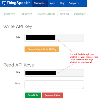
Step-7: Now we will see how to log data and read data to and from this channel. Browse to the API Keys tab for your channel. Note down the read and write api_keys (as shown below), as you will need it for posting and reading data to ThingSpeak. I have obscured the api keys for my channel intentionally. Never share your channel api keys with unintented recipients as they might spam the channel inadvertently ;)

Create New ThingSpeak Channel

Step-8: Use the following URL format to log data to ThingSpeak.

https://api.thingspeak.com/update.json?api_key=<your-write-api-key>&field1=58

Upon hitting the above URL, the data '58' will get logged in the ThingSpeak IoT cloud. You will see the below response on your browser.

How to use ThingSpeak for IoT

Correspondingly, you can also see the logged data in the ThingSpeak channel's Private/Public View tabs, as shown below.


Step-9: Use the following URL format to read the logged data from ThingSpeak.

http://api.thingspeak.com/channels/<your-channel-id>/feeds.json?key=<your-read-api-key>&results=1

On hitting the above URL in the browser, you will receive the last posted data row from ThingSpeak, as shown below.


To conclude, I hope you liked this post on creating a device channel in ThingSpeak. I love hearing from you, so don't forget to leave your comments and share your experience using the ThingSpeak IoT cloud.

Cheers!
KBRC

Using ESP8266 with Arduino Uno

Using the ESP8266 with Arduino Uno is one of the fundamental methods of connecting edge devices (aka. "things") to the internet. We will use a chip called the ESP8266 (this is a Wifi capable chip with a built-in antenna) with the Arduino Uno, for logging messages to an IoT Cloud platform. For the purpose of this demonstration we will use a free IoT platform called ThingSpeak. However, you are free to choose from AWS, Azure, Dweet, Particle, your own "bespoke" stuff or many more out there. I chose ThingSpeak because it was absolutely free (no Credit Card needed for signing up). However, the limitation of the ThingSpeak IoT platform, atleast the free stuff I am using here, is of accepting ONLY ONE incoming message per 15 seconds - so in one minute you will be able to send a maximum of 4 messages only.

A Word Of Caution

This is an advanced setup for connecting the ESP8266 with the Arduino Uno, not recommended without a good understanding first - one small mistake and the ESP8266 chip (3.3V) might get fried (if unfortunate). Using the ESP8266 with the Arduino (5V) is fundamentally different from using any other 5V compatible component, because of the multiple voltage levels involved in this circuit setup.

Dos & Don'ts

 While setting up the ESP8266 with Arduino Uno, always use a separate power source for connecting the ESP8266 to the Arduino Uno. Do not use the 3.3V power supply from Arduino. The ESP8266 operates on 3.3V DC, whereas the Arduino Uno operates on 5V DC. The ESP8266 requires currents much greater (120 - 170 mA while transmitting wireless packets - refer Page 19 of the manufacturer's datasheet) than what can be supplied by an Arduino Uno 3.3V pin (~50mA - refer this for details). Hence you will have to grasp the following fundamentals.
  • Using Multiple Power Sources in the same circuit - Powering the Arduino board from a 5 V power source and ESP8266 from a 3.3V power source.
  • Common Grounding - How to give the Arduino board and the ESP8266 chip a common GROUND, even though they are powered from two different power sources?
  • Voltage Division - How to reduce 5V to 3.3V using the Voltage Division Technique for connecting the Arduino Tx Pin (5V) to ESP8266 RXD Pin (3.3V)?
In the following sections we will see how to actually hook up the ESP8266 with the Arduino Uno, in the wiring diagram below.

Hardware Needed
  • Arduino UNO
  • USB A to B cable (for programming the Arduino UNO)
  • Breadboard
  • Jumper Wires (M2M, M2F and F2F)
  • ESP8266
  • FT232RL USB to TTL Converter (for configuring the ESP8266)
  • USB A to mini B cable (for connecting the FT232RL USB to TTL converter)
  • DC/DC Step-Down 3.3V Converter (alternately you may use an AMS1117 3.3V regulator and some capacitors, but it is a bit advanced)
  • AAA Battery Holder (for 4 x 1.5V batteries)
  • 4 Pcs. of 1.5V Batteries
  • Soldering Kit (you may need this to join the power supply wires to some header pins)
  • Multimeter (to check the output of the 3.3V voltage converter really 3.3V or not...I am a bit paranoid while working with off the shelf electronic components)

Software Needed
  • Arduino IDE
  • IoT Cloud Channel
Here onwards, we will proceed gradually, one step at a time, for connecting the ESP8266 with Arduino Uno. Basically we will have to take the following steps in order to push data into the IoT cloud platform:
  • Configure the ESP8266
  • Wire the ESP to the Arduino
  • Setup a Channel (for each edge device) in the IoT Cloud
  • Write a C program for using the ESP8266 from the Arduino board

Configuring the ESP8266

This is a very important step in this setup and must be performed before connecting the ESP8266 with the Arduino Uno. The baud rate of your ESP8266 should be set to 9600, so that you can communicate with it via your Arduino IDE's Serial Monitor and also via the Software Serial while issuing AT commands for connecting from the C program to the internet. You can refer to the steps to configure the ESP8266 hrer.

Wiring the ESP8266 with the Arduino UNO

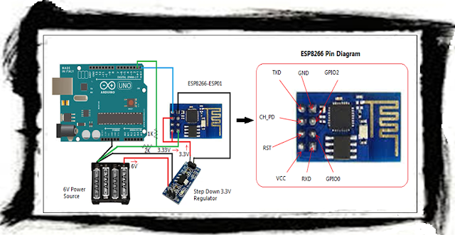
         While wiring the ESP8266 with the Arduino Uno, exercise caution while connecting this setup. Make sure that any voltage into the ESP8266 chip is around 3.3 volts. Use a multimeter to double check the voltage. The remaining setup shown below is self-explanatory for wiring the ESP8266 with the Arduino Uno.

ESP8266 with Arduino UNO
Figure 4 - Wiring of ESP8266 with Arduino Uno 

Wire the ESP8266 to the Arduino UNO as described below:

  • Arduino TX --> ESP RXD (using voltage division method) and then into Common GND - the GREEN line shown in the picture
  • ESP TXD --> Arduino RX (no voltage shifting needed) - the BLUE line shown in the picture
  • Arduino GND --> Common GND (-ve Terminal of power source)
  • ESP GND --> 3.3V Step-Down Regulator  GND
  • ESP VCC & CH_PD --> 3.3V Step-Down Regulator VOUT
  • 3.3V Step-Down Regulator VIN --> +ve Terminal of power source
  • 3.3V Step-Down Regulator --> -ve Terminal of power source

Setting up a ThingSpeak Channel

          After connecting the ESP8266 with Arduino Uno, the next thing that you will have to do is to create an account in an IoT Cloud platform, so that you may use it to log the data from the edge device (node MCU as they call it sometimes) or sensor, using the ESP8266 with Arduino Uno. For this purpose, I will be using www.ThingSpeak.com to demonstrate how the setup a channel to receive data from a device. The term "channel" in the context of an IoT cloud simply means an endpoint (an exposed web service and/or web service method) to receive data from the sensor. Hence for each device you will have to create a corresponding channel. I will write a dedicate post on setting up and configuring the ThingSpeak account and channel, at a later time. For now I will provide the minimum information needed to log data from a sensor to the cloud. After creating your account, create a New Channel and then configure it by following the on screen instructions. Once the new channel is created it will appear in your account's My Channels dashboard (Channels > My Channels), as shown below.

ESP8266 with Arduino UNO
Figure 5 - ThingSpeak Channel for receiving data from ESP8266 with Arduino Uno

          Next, step is to find out the how to log and read data to and from this channel. ThingSpeak provides several ways to integration data, such as:
  • Simple GET and PUT using URLs from a browser
  • Simple GET and PUT from JavaScript or any other code
  • It also provides a library (the C header file - ThingSpeak.h) for use with an Arduino Uno
          For a quick flavour of how to log and read data consider the following simple examples based on hitting URLs from your browser window. Remember to replace your api_key in appropriate places below. You will be alloted an api_key once you create a channel in ThingSpeak - it is basically a public key that secures your channel from accepting data from an unintended source.

Logging Data:
https://api.thingspeak.com/update.json?api_key=<your-write-api-key>&field1=58

Reading Data (this URL format will return the last logged data row):
https://api.thingspeak.com/channels/<your-channel-id>/feeds.json?key=<replace-with-your-api-key>&results=1


The C Program for Posting Data to ThingSpeak

Use the following C program for using the ESP8266 with Arduino Uno, to read the sensor data and then log it to the ThingSpeak IoT cloud. In this example, we are not going to use either the ThingSpeak API or the ESP8266 API for Arduino. We will use only AT commands.


Conclusion

          In conclusion, using the ESP8266 with the Arduino Uno will pose some practical challenges for the IoT prototypist. Specially, using multi-voltage devices in the same circuit. I hope you find this post useful. Do leave your comments and experiences below. I would love to hear from you!

Cheers!
KBRC
Temperature Sensor with Arduino Uno


In the previous post we saw how to measure temperature using the DHT11 temperature sensor with the Arduino UNO. In this post we will discuss and see how to use a basic temperature sensor for detecting higher than normal or "fire-like" heat/temperatures (a potential emergency). As usual we will use our favorite prototyping equipment, the Atmel chip based Arduino Uno (you may use an 8-bit PIC family processor also as an alternative, but then you will have to use MPLAB for burning the C programs and some USB to TTL programmer hardware) for writing the embedded C programs to interface with the sensors.

Which Temperature Sensor should I use?

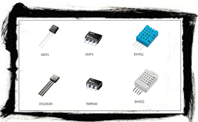
Well, it is tricky. There are a myriad of temperature sensors available in the industry that may be used with an Arduino UNO. Each of them differ mainly on two grounds: accuracy and operating conditions. If you are planning the devise a particular IoT solution at a particular geographical location or weather condition, then carefully evaluate the datasheets of these sensors. A snapshot image of six commonly used temperature sensors is provided below.

DHT11 Temperature Sensor with Arduino UNO
Figure 1 - Commonly used Temperature sensors.
For the purpose of this demonstration, I will use the DHT11 temperature sensor with Arduino UNO, partly because I had it lying around from an old kit. However, this sensor is not very accurate as it can give readings that are off by 2 degrees celcius (+/-). Also DHT11 can measure a maximum of 50 degrees celcius, so it is not a very good detector of "fire-like" heat. Instead use DHT22 (based on DS18B20) has better range for sensing "fire-like" temperatures. You may refer to the DHT11 datasheet here. By the way, the DHT11 can also be used to sense relative humidity, however, we will not use this feature for our Smart City Emergency Response System project. For a more accurate temperature sensing, you may evaluate the datasheets of other sensors before employing them. Just search for the term - "DHT22 datasheet", for example, in google/bing.

How to connect/wire a DHT11 Temperature sensor with an Arduino?

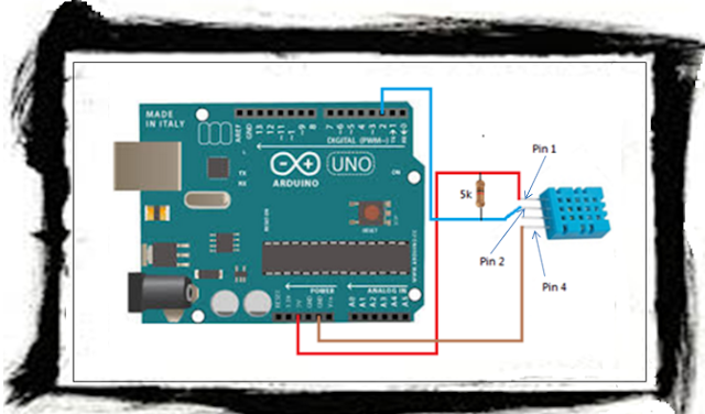
We will be using the DHT11 temprature sensor with Arduino UNO for our experiment. Given below is my account of using this sensor. The DHT11 sensor has 4 pins (remember Pin 3 in not used), the wiring for the sensor and the Arduino board is shown below. One important point to note is the mention of connecting a pull-up resistor, as shown in the snapshot taken from the DHT11 datasheet in the Figure  below. This point is a source or some confusion, as I found in a lot of forums over the internet. However, it is as simple as just joining Pin 1 to Pin 2 using a 5K resistor (as shown in Figure 3 below), if the length of the cables is below 20 mtrs (which was the case in my experimental setup).

DHT11 Temperature Sensor with Arduino UNO
Figure 2 - Suggested Wiring from DHT11 Datasheet
Given below is how I wired the DHT11 sensor to my micro-controller board the Arduino Uno.

DHT11 Temperature Sensor with Arduino UNO
Figure 3 - Actual wiring of a DHT11 temperature sensor with an Arduino board

You should connect them as follows:

DHT11 Sensor          Arduino
----------------          ----------
Pin 1                 --->   5V
Pin 2                 --->   Pin 2
Pin 3                 --->   (not used)
Pin 4                 --->   GND

NOTE - Remember to connect the resistor between Pin 1 and Pin 2 of the DHT11 sensor.


Embedded C Program for reading the DHT11 Temperature sensor

There is a pre-requisite of installing the DHT11 library, for using the DHT11 temperature sensor with Arduino UNO. Follow these steps to first install the DHT library. You will need this library in order to include the DHT.h file in the sketch below.

  • Launch the Arduino IDE.
  • Navigate to Sketch > Include Library > Manage Libraries...
  • The Library Manager window will pop up.
  • In the Library Manager window, search for DHT and install the required library. The library that I choose to install is shown below.
DHT11 Temperature Sensor with Arduino UNO
Figure 4 - Screenshot of Installed DHT Sensor Library in Arduino IDE Library Manager


Next you may use the following sketch for reading values from the DHT11 temperature sensor with Arduini Uno. The below code reads the DHT11 temperature sensor values at 5 second intervals and checks whether the temperature exceeds 65 degrees celcius (or 149 degrees farenheit). However, proper calibration and consultation with fire experts is necessary for a working threshold for fire temperatures.


Conclusion

To conclude this post, we have seen how yu may use a DHT11 temperature sensor with the Arduino UNO platform. Once the alert has been detected, you will have to take some suitable action such as (but not limited to):
  • Sounding an alarm
  • Posting the alert to an IoT cloud platform
  • Activating some defence mechanism (such as sprinklers in case of fire)
  • Sending SMS and calling phone numbers

Smoke Detector with Arduino Uno

In this post we will discuss and see how to use a Smoke Detector / Sensor with Arduino Uno for detecting smoke. As usual we will use our favorite prototyping equipment, the Atmel chip based Arduino Uno (you may use an 8-bit PIC family processor also as an alternative, but then you will have to use MPLAB for burning the C programs and some USB to TTL programmer hardware) for writing the embedded C programs to interface with the sensors. Before jumping into the wiring and code for using a Smoke Detector / Sensor with Arduino Uno, a short video of my experiement with smoke detector / sensor using an incense stick is provided below. In the video you will notice that once smoke is detected, an alert saying "Smoke detected" is displayed in the serial window of the Arduino IDE.


Connect a Smoke Detector / Sensor with an Arduino Uno?

We will be using the MQ-2 series Gas/Smoke detector / sensor with Arduino Uno, for our experiment. The MQ-2 sensor has 4 pins, the wiring for the sensor and the Arduino board is shown below. In case you want to use the Digital output pin (D0) then remember to use the gas sensitivity adjustment potentiometer (can be found on the reverse side of the chip) as per your requirement. Otherwise, if you are using the Analog output pin to read the sensor then no need for using the in-built potentiometer. Use the gas sensitivity graph on Page 2 of the datasheet here to play around with the threshold values in the program below. Not only gas/smoke, but you can also detect other types of gases. Given below is my account of using this sensor. For more details on gas sensor you may refer this site.

MQ2 Smoke Detector / Senor with Arduino Uno
Figure 1 - Wiring an MQ-2 Smoke detector / sensor with an Arduino Uno


You should connect them as follows:

MQ-2 Sensor          Arduino
----------------          ----------
Vcc                 --->   5V
GND               --->   GND
D0                   --->   (not used)
A0                   --->   A0

Embedded C Program for reading the Smoke detector / sensor with Arduini Uno

You can use the following sketch for reading the Smoke detector / sensor with Arduini Uno. However, do some self testing and calibration with the threshold values.


Conclusion

Using the above example you should be able to use the MQ2 Smoke detector / sensor with and Arduino Uno. Once the alert has been detected, you will have to take some suitable action such as (but not limited to):
  • Sounding an alarm
  • Posting the alert to an IoT cloud platform
  • Activating some defence mechanism (such as sprinklers in case of fire)
  • Sending SMS and calling phone numbers

Smart City - IoT Based Connected Emergency Response System

Today we will see one of the fundamental approaches of connecting various edge devices to the internet and thus achieve our first step toward the Internet-of-Things. We will use the following scenario to demonstrate the concept. This post is the opening article (1 of 10 planned posts) for a series in-depth technical (with electronics and code, of course!) articles on this Smart City topic. In this post we will see a detailed overview of WHAT needs to be done. The posts that follow in future, we will take up each technical topic and look at it in details. At the end of this series of posts the idea will be to develop a fully working prototype of the envisaged scenario.

SCENARIO: Smart City - IoT Based Connected Emergency Response System

Imagine a Smart City framework where all public places are subscribed to a central fire alert system. And in turn emergency response services (Fire Department in this example) are alerted automatically. The following diagram is self-explanatory with numbered series of steps (1 through 11) to depict the process flow in case of a Fire emergency. Also in this example we are not using GSM modules, instead we are using the ESP chip and taking the Wi-Fi route. In a furture post I will write about the GSM module in the case of a Wild Forest Fire Early Alarm System.

Figure 1 - Smart City - IoT Based Connected Emergency Response System

For building this system, we will require different categories of things - both hardware and software. In the following section we will see the different types of things that will be required.

Hardware:
  • SensorsMQ2 Series Gas/Smoke Sensor, DHT Series Heat Sensor and LDR based light sensor. This combination of 3 sensors will act as a compound sensor for detecting fire (Smoke, Heat and Light).
  • Controller: Arduino UNO (only during the prototyping of the individual sub-units), for the full blown project use Arduino Mega because we will require a lot of GPIOs (General Purpose Input Output Pins) in order to control all the peripheral devices.
  • Fire Defence System: Sprinkler fitted with a Solenoid Valve - a Solenoid Valve can be opened and closed electrically, a 12V Optocoupler Relay for switching the solenoid valve ON/OFF, a Piezo Buzzer (for making shrill beeps at high frenquency) and some basic electronics (resistors and transistors - we will see in detail in the following posts).
  •  Internet Enabler: ESP8266-ESP01 Wi-Fi chip and AMS1117 3.3V step-down voltage regulator for connecting the Tx Pin (from Arduino) to Rx Pin (of the ESP8266-ESP01). There are atleast 12 versions of the ESP chip, each version comes with its own bells and whistles. For now let us use the basic stuff i.e. ESP01.
  • Wi-Fi Router: A Wi-fi network for Internet connectivity.
  • Power Source(s): You will need the following 3 types of power sources. One 5V, 1A AC to DC Adapter (for Arduino, Sensors and Piezo Buzzer)and another 3.3V, 60 - 650 mA AC to DC Adapter (for the ESP8266). Use the third power source with "great" caution - AC mains (for the Solenoid Valve via the Optocoupler Relay). 

Software:
  • Programming IDE: Arduino IDE - we will use this to write code (using C language), compile and flash (push/embed the C program into the micro-controller).
  • Cloud Platform: ThingSpeak/Dweet/Azure IoT Hub. We will use either one of these. The future posts will make the choice. The cloud platform will be used to log the alerts from the edge devices.
  • Responsive Web App: HTML5, Bootstrap, CSS3, JQuery, AJAX - This will be a local webpage (no need to host a website for prototyping phase), capable of polling the logged alerts in the cloud database and displaying the results on the browser.

Sub-Components (to be covered in future posts):

Tying all the above components we can easily build a Smart City - Connected Emergency Response System. I have linked some relevant posts for the above sub-units.

Cheers!
KBRC

Arduino - Reverse Car Parking Alarm

As promised in the previous post, we will be building a Reverse Parking alarm for cars. For doing so we will utilize the same wiring scheme as in my previous post. However, we will change the C sketch slightly. The change in the C code will be to start beeping the Piezo Buzzer at longer intervals when the Car is 30 centimeters (1 feet) away from an object, followed by intensifying the beeping at shorter intervals as the Car comes closer to the obstacle. Watch the Youtube video of the sample project below.


Setup the wiring for the reverse parking alarm as described in my previous post. Followed by using the C program written below.


Hope you enjoyed this article! Please share and comment on this post if you found it useful. I would love to hear from you.

Cheers,
KBRC

Arduino - How to detect obstacles/objects and react?

How to detect an obstacle with an Arduino and HC-SR04 Ultrasonic Module?

In this post we will detect an obstacle using the HC-SR04 Ultrasonic Ranging module with an Arduino. Basically, we will write an embedded C program for Arduino to read the Ultrasonic sensor data every second, followed by converting the sensor data into distance and in the end run a piece of logic that if the detected object (i.e. motion due to moving object) is within 10 centimeters then a Piezo Buzzer will be beeped. Check out the Youtube video below demonstrating my experiment with detecting motion.


The breadboard setup for detecting an obstacle has been provided below as a reference. You may use this wiring scheme for hooking up your HC-SR04 along with the Piezo Buzzer to your Arduino. Be careful not to connect the wrong wires, as it might result in a short circuit.


Figure 1 - Breadboard Wiring for obstacle detection 

The figure below shows the schematic wiring diagram for detecting an obstacle.


Figure 2 - Schematic wiring for obstacle detection

Join the wiring as follows:
  • HC-SR04: Connect Vcc (on HC-SR04) to 5V (on Arduino)
  • HC-SR04: Connect Gnd (on HC-SR04) to Gnd (on Arduino)
  • HC-SR04: Connect Trig (on HC-SR04) to Pin 4 (on Arduino)
  • HC-SR04: Connect Echo (on HC-SR04) to Pin 12 (on Arduino)
  • Piezo Buzzer: Connect the + Terminal (Longer leg) to Pin 8 (on Arduino)
  • Piezo Buzzer: Connect the - Terminal (Shorter leg) to Gnd (on Arduino)

That C sketch for detecting an obstacle with the Arduino is very simple and is provided for reference below.


Hope you enjoyed this post. Please share this post if you found it useful and write your comments below this post. I would love to read your your thoughts and experiences with the HC-SR04 Ultrasonic Ranging module.

In my next post, I will show you how you can use your Arduino and HC-SR04 to create a reverse parking alarm for a car!

Cheers!
KBRC

Arduino - How to measure distance?

How to measure distance using Arduino?

In this post we will look at measuring distances using an Ultrasonic sensor with the Arduino. For this purpose, I have chosen a commonly available sensor module called the HC-SR04 Ultrasonic Ranging Module. There are other Ultrasonic sensor as well, that give better field performance. However, we will start off with the HC-SR04. Given below is a picture of the HC-SR04 module. The HC-SR04 is an ultrasonic ranging module capable of measuring distances using Ultrasonic sound waves and it can be interfaced with not only the Arduino, but also various micro-controllers.


In one of my future posts, I will explain how we can hook  up the HC0SR04 with an ESP8266 Wifi Module and make it behave like a local web server, thereby reducing the costs of having a costly edge device for data acquisition.

Figure 1 - The HC-SR04 Ultasonic Module

There are various applications that may be developed using this Ultrasonic module with the Arduino. In these series of posts, we will analyze this module with the Arduino from various angles: Basic programming, Specifications Testing and then look at some Automation Solutions. For this post we will only look at basic distance measurement.

Basic Programming and Interfacing

The basic programming is straight forward and has two steps: setting up the circuit and writing the sketch/program. Build the circuit as shown below. This is a schematic provided to help you in wiring up.


Figure 1 - Wiring Schematic Diagram

Connect the PINS as described below:
  • Connect Vcc (on HC-SR04) to 5V (on Arduino)
  • Connect Gnd (on HC-SR04) to Gnd (on Arduino)
  • Connect Trig (on HC-SR04) to Pin 8 (on Arduino)
  • Connect Echo (on HC-SR04) to Pin 12 (on Arduino)


Next use the following sketch. Compile and load the following into your Arduino.


In order to test the system, keep your Arduino plugged in with your computer, and open your Arduino IDE's Serial Monitor window (Tools > Serial Monitor) - the serial monitor will show you the output from the print() and println() function calls in the running sketch. The running sketch will keep reading the sensor data, do some calculations and print the distance of the object in front of the sensor at regular intervals. Place/move some objects in front of the sensor and keep watching the serial monitor window.

See for yourself what gets printed on the Serial Monitor window, as you move the object(s) away from the sensor and bring them near the sensor. I will be eager to read and learn from your experiences, so please put your comments below.

In the next post we will see how to detect an obstacle and react using this Ultrasonic module.


Cheers,
KBRC


Basics of Embedded/IoT Circuit Electronic Components


<< Previous Visit my Traditional Programming Blog Next >>

Okay so before jumping into the embedded IoT world, one must know a few things regarding how to hook up basic circuits and also understand some commonly used basic electronic components and also why and how they are used.

When starting to tinker with embedded systems, unless from an electrical/electronics background, one has to research a bit in order to grasp the whys and hows of adding electronic components in the prototyping circuitry. In this post, I will try to provide a gist of the bare minimum things you need to understand before diving into working with electronic circuits.

The most commonly encountered electronic components while bread boarding (this itself is one of the topics) are:

  • Resistors
  • Transistors
  • Semiconductor Diodes

Use of Resistors

Resistors are used to reduce the amount of current. To draw an analogy you may think of them as a Firewall that reduces the amount of traffic. Or as an obstruction in the path of flowing water. Or just something that obstructs and reduces the flow of current - I tried to make it simple! So coming back to the topic, the thumb rule is if you are adding a delicate electronic component in the circuit that cannot withstand too much current, then we must add appropriate resistors before the component so that the resistor can resist (and dissipate) the input current and allow a reduced current to flow out to the delicate component. For example, in my earlier post I cautioned regarding placing resistors before LEDs, otherwise they will burn out.

Figure 1 - Resistors

The classical formula for calculating the value of a resistor required is provided below for reference. However, as a beginner, do not attempt the calculations; instead use the specified resistors from a circuit diagram.

                    Resistance = Voltage (from source) / Max. Tolerable Current

The two ends of a resistor do not have any polarity. You may place a resistor in any direction in your circuits.

Also you will have to get used to determining the value of a resistor by looking at the color bands. In the beginning, when you work out of a starter kit everything will be fine for a few weeks as all the resistors will come properly labelled. However, after a few months, as you start building more prototypes it is very likely to lose track of which one is which. In order to avoid any confusion, additional reading is suggested online, for decoding the resistor color bands and finding out its total value.

Use of Transistors

Transistors are commonly used for switching. By switching, I literally mean switching. It acts just like a physical ON/OFF switch. Trying to understand transistors can get academically demanding, hence I will try to stick to the basics...only to the extent needed to start with for building your circuits. You are encouraged to engage in advanced self study if you desire so.

A typical transistor has 3 legs, known as: Collector, Base and Emitter. The most common types of transistors are classified as PNP and NPN transistors. If you hold the flat face of a transistor towards your face then for a PNP type transitor the legs are arranged in the order: Collector, Base and Emitter (from left to right); whereas in case of a NPN transistor the legs are arranged as Emitter, Base and Collector (from left to right).

Figure 2 - Showing a PNP and NPN transistor


A transistor is built in such a unique way that internally there is a circuit between the Emitter, Base and Collector. Normally, a transistor's internal circuit is in a open (non conductive state) state. However, when a small voltage is applied on the Base, the internal circuit between the Emitter, Base and Collector gets closed (conductive state). Thus a transistor acts as a switch and gets activated (closed conductive state) when a voltage is applied on the base. In layman terms, applying a voltage on a transistor's base is like lifting/pressing a physical light bulb switch to ON position with your finger.

Use of Semiconductor Diodes

Diodes in general are of many types and is a separate topic and out of scope of this context, hence we will proceed with the basic understanding and build upon it as we proceed. We will ficus on Semiconductor Diodes for our purpose.

Primary function of a semiconductor diode is to act just like a check valve allowing current to flow in one direction and resisting (up to a limit) current from flowing in the opposite direction. Think of it as a "one way" lane in the direction of current permitted. Or think of it like a piece of cloth stuffed into a water pipeline that can only hold the water until it gets saturated, in the opposite direction.

Figure 3 - Shows some Semiconductor Diodes

Sometimes under certain situations a reverse current is generated - such as when a motor armature is stopped it continues to spin (due to inertia) inside the motor case until it comes to a halt. This reverse current has the potential to flow back into other electronic components (worse if it reaches your Arduino pins) - this might lead of damage. In order to stop this reverse current from flowing back, a diode is placed in a appropriate manner in the circuit. Rule of thumb is to face the banded end of the diode towards the source that has the potential to generate reverse current.

You must adhere to circuit specifications carefully while using diodes, as all diodes are not the same and may behave very differently, pay special attention to the model number specified for a particular setup.

I hope you found this post helpful to get you started. Please share your comments and reactions below.

Cheers!
KB