I was working on an Arduino and ESP8266 project, during
that time I had to setup the FTDI FT232RL USB to TTL converter on my laptop. Normally, you will need the FTDI FT232RL USB to TTL converter for talking to other chips from your computer and you can also use it to push programs into other micro-controller boards.

Given below is the first-hand account of my experience setting up this device on my laptop. Setting up the FTDI FT232RL USB to TTL converter chip is a 2 step process:
- Step-1: FT232R USB UART Installation
- Step-2: USB Serial Port Installation
Pre-Requisites
The pre-requisite step, for setting up the FTDI FT232RL USB to TTL Converter. was to download and install the correct
software driver for the FTDI FT232RL USB to TTL converter. The driver is
available on the FTDIChip website. You may browse to the driver download link here and download a compatible (for your operating system) version of the driver.
My laptop was powered by Windows 7’s 64-bit version. I used
the x86 (32-bit), v2.12.18 driver for Windows. A snapshot taken from the
FTDIChip website tabulating various drivers available for the FTDI FT232RL USB
to TTL converter is shown below.
Step-1: FT232R USB UART Installation
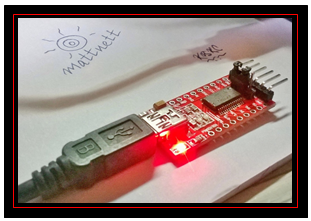
The first step, for setting up the FTDI FT232RL USB to TTL Converter, is to connect the FTDI FT232RL USB to TTL converter
to my laptop/PC using a USB A (on the laptop/PC side) to USB Mini B (on the FTDI
FT232RL USB to TTL converter side) cable.
After making the basic cable connection, for setting up the FTDI FT232RL USB to TTL Converter, you will notice
that the LED on the FTDI FT232RL USB to TTL converter starts glowing.
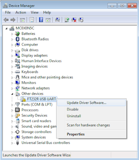
Now from your laptop/PC, navigate to Control Panel >
Device Manager. In the Device Manager window you will notice a node named “Other
devices”, under that there will be a device listed as “FT232R USB UART” –
however, the device will have a yellow icon against it indicating that it is
not yet ready to be used.
In order to install the downloaded device driver, simply
right-click on the device listing, and choose the “Update Driver Software…” option
from the context menu, as shown below.

After the installation, you will receive the
following message that the device installation was successful.


Thereafter, follow the on-screen instructions, in order
to install the FTDI FT232RL USB to TTL Converter. During the installation, remember
to point to just the base (top level/starting) folder location (pointing to an
exact file is not required) where you had downloaded and unzipped the driver
files.

However, at the same time you will also notice that there
is a pop up notification in the System Tray saying that the installation was
not successful. Do not get confused by this behavior, as I already told you
that setting up the FTDI FT232RL USB to TTL converter chip is a two step
process. As a next step, we will now proceed to install the port.
Step-2: USB Serial Port Installation
Once again, for setting up the FTDI FT232RL USB to TTL Converter, browse to the Device Manager and navigate to
the “Other devices” node. You will notice that the name of the device has
changed to “USB Serial Port” this time. Right-click on the “USB Serial Port”
and just like in Step-1, choose the “Update Driver Software” option from the
context menu.
This time also provide the same base folder path, just
like you did in Step-1 for setting up the FTDI FT232RL USB to TTL Converter. The USB Port driver is also in that same location.
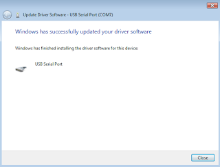
Follow the on-screen instructions and complete the installation. After the
installation completes successfully, you will be greeted with the following
screen.
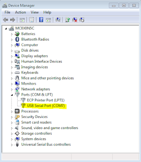
Go back to the Device Manager window and find the newly
installed FTDI FT232RL USB to TTL converter, as shown below. In my case, it was
listed as “USB Serial Port (COM7)”.
Conclusion
You are all set to use your FTDI FT232RL USB to TTL converter to talk to other chipsets, via any serial monitor.


Thanks for your information. I hooked up mine to my windows 10 pro. And it shows it as com port 9 which comes and goes when you plug and it plug it. Does not have a yellow flag and under properties. I have not tried to connect it to anything yet. Big question is RTS and CTS are not both on the row of 90 degree pins. There are all kinds of connections down the sides. I need to connect to a serial device that uses ground plus rxd and txd with CTS and RTS shorted together. Wondering if RTS and CTS on the side rows are part of the 90 degree pin capabilities? Would wonder if there is a manual for this device?
ReplyDelete