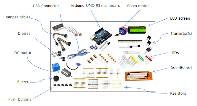
Okay so before jumping into the embedded IoT world, one must know a few things regarding how to hook up basic circuits and also understand some commonly used basic electronic components and also why and how they are used.
When starting to tinker with embedded systems, unless from an electrical/electronics background, one has to research a bit in order to grasp the whys and hows of adding electronic components in the prototyping circuitry. In this post, I will try to provide a gist of the bare minimum things you need to understand before diving into working with electronic circuits.
The most commonly encountered electronic components while bread boarding (this itself is one of the topics) are:
- Resistors
- Transistors
- Semiconductor Diodes
Use of Resistors
Resistors are used to reduce the amount of current. To draw an analogy you may think of them as a Firewall that reduces the amount of traffic. Or as an obstruction in the path of flowing water. Or just something that obstructs and reduces the flow of current - I tried to make it simple! So coming back to the topic, the thumb rule is if you are adding a delicate electronic component in the circuit that cannot withstand too much current, then we must add appropriate resistors before the component so that the resistor can resist (and dissipate) the input current and allow a reduced current to flow out to the delicate component. For example, in my earlier post I cautioned regarding placing resistors before LEDs, otherwise they will burn out.
 |
| Figure 1 - Resistors |
The classical formula for calculating the value of a resistor required is provided below for reference. However, as a beginner, do not attempt the calculations; instead use the specified resistors from a circuit diagram.
Resistance = Voltage (from source) / Max. Tolerable Current
The two ends of a resistor do not have any polarity. You may place a resistor in any direction in your circuits.
Also you will have to get used to determining the value of a resistor by looking at the color bands. In the beginning, when you work out of a starter kit everything will be fine for a few weeks as all the resistors will come properly labelled. However, after a few months, as you start building more prototypes it is very likely to lose track of which one is which. In order to avoid any confusion, additional reading is suggested online, for decoding the resistor color bands and finding out its total value.
Use of Transistors
Transistors are commonly used for switching. By switching, I literally mean switching. It acts just like a physical ON/OFF switch. Trying to understand transistors can get academically demanding, hence I will try to stick to the basics...only to the extent needed to start with for building your circuits. You are encouraged to engage in advanced self study if you desire so.
A typical transistor has 3 legs, known as: Collector, Base and Emitter. The most common types of transistors are classified as PNP and NPN transistors. If you hold the flat face of a transistor towards your face then for a PNP type transitor the legs are arranged in the order: Collector, Base and Emitter (from left to right); whereas in case of a NPN transistor the legs are arranged as Emitter, Base and Collector (from left to right).
 |
| Figure 2 - Showing a PNP and NPN transistor |
A transistor is built in such a unique way that internally there is a circuit between the Emitter, Base and Collector. Normally, a transistor's internal circuit is in a open (non conductive state) state. However, when a small voltage is applied on the Base, the internal circuit between the Emitter, Base and Collector gets closed (conductive state). Thus a transistor acts as a switch and gets activated (closed conductive state) when a voltage is applied on the base. In layman terms, applying a voltage on a transistor's base is like lifting/pressing a physical light bulb switch to ON position with your finger.
Use of Semiconductor Diodes
Diodes in general are of many types and is a separate topic and out of scope of this context, hence we will proceed with the basic understanding and build upon it as we proceed. We will ficus on Semiconductor Diodes for our purpose.
Primary function of a semiconductor diode is to act just like a check valve allowing current to flow in one direction and resisting (up to a limit) current from flowing in the opposite direction. Think of it as a "one way" lane in the direction of current permitted. Or think of it like a piece of cloth stuffed into a water pipeline that can only hold the water until it gets saturated, in the opposite direction.
 |
| Figure 3 - Shows some Semiconductor Diodes |
Sometimes under certain situations a reverse current is generated - such as when a motor armature is stopped it continues to spin (due to inertia) inside the motor case until it comes to a halt. This reverse current has the potential to flow back into other electronic components (worse if it reaches your Arduino pins) - this might lead of damage. In order to stop this reverse current from flowing back, a diode is placed in a appropriate manner in the circuit. Rule of thumb is to face the banded end of the diode towards the source that has the potential to generate reverse current.
You must adhere to circuit specifications carefully while using diodes, as all diodes are not the same and may behave very differently, pay special attention to the model number specified for a particular setup.
I hope you found this post helpful to get you started. Please share your comments and reactions below.
Cheers!
KB


