Temperature Sensor with Arduino Uno


In the previous post we saw how to measure temperature using the DHT11 temperature sensor with the Arduino UNO. In this post we will discuss and see how to use a basic temperature sensor for detecting higher than normal or "fire-like" heat/temperatures (a potential emergency). As usual we will use our favorite prototyping equipment, the Atmel chip based Arduino Uno (you may use an 8-bit PIC family processor also as an alternative, but then you will have to use MPLAB for burning the C programs and some USB to TTL programmer hardware) for writing the embedded C programs to interface with the sensors.

Which Temperature Sensor should I use?

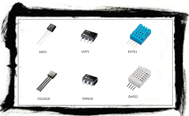
Well, it is tricky. There are a myriad of temperature sensors available in the industry that may be used with an Arduino UNO. Each of them differ mainly on two grounds: accuracy and operating conditions. If you are planning the devise a particular IoT solution at a particular geographical location or weather condition, then carefully evaluate the datasheets of these sensors. A snapshot image of six commonly used temperature sensors is provided below.
DHT11 Temperature Sensor with Arduino UNO
Figure 1 - Commonly used Temperature sensors.
For the purpose of this demonstration, I will use the DHT11 temperature sensor with Arduino UNO, partly because I had it lying around from an old kit. However, this sensor is not very accurate as it can give readings that are off by 2 degrees celcius (+/-). Also DHT11 can measure a maximum of 50 degrees celcius, so it is not a very good detector of "fire-like" heat. Instead use DHT22 (based on DS18B20) has better range for sensing "fire-like" temperatures. You may refer to the DHT11 datasheet here. By the way, the DHT11 can also be used to sense relative humidity, however, we will not use this feature for our Smart City Emergency Response System project. For a more accurate temperature sensing, you may evaluate the datasheets of other sensors before employing them. Just search for the term - "DHT22 datasheet", for example, in google/bing.

How to connect/wire a DHT11 Temperature sensor with an Arduino?

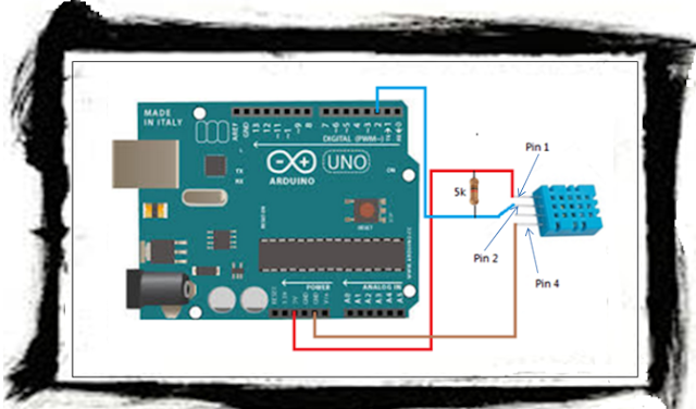
We will be using the DHT11 temprature sensor with Arduino UNO for our experiment. Given below is my account of using this sensor. The DHT11 sensor has 4 pins (remember Pin 3 in not used), the wiring for the sensor and the Arduino board is shown below. One important point to note is the mention of connecting a pull-up resistor, as shown in the snapshot taken from the DHT11 datasheet in the Figure  below. This point is a source or some confusion, as I found in a lot of forums over the internet. However, it is as simple as just joining Pin 1 to Pin 2 using a 5K resistor (as shown in Figure 3 below), if the length of the cables is below 20 mtrs (which was the case in my experimental setup).

DHT11 Temperature Sensor with Arduino UNO
Figure 2 - Suggested Wiring from DHT11 Datasheet
Given below is how I wired the DHT11 sensor to my micro-controller board the Arduino Uno.

DHT11 Temperature Sensor with Arduino UNO
Figure 3 - Actual wiring of a DHT11 temperature sensor with an Arduino board

You should connect them as follows:

DHT11 Sensor          Arduino
----------------          ----------
Pin 1                 --->   5V
Pin 2                 --->   Pin 2
Pin 3                 --->   (not used)
Pin 4                 --->   GND

NOTE - Remember to connect the resistor between Pin 1 and Pin 2 of the DHT11 sensor.


Embedded C Program for reading the DHT11 Temperature sensor

There is a pre-requisite of installing the DHT11 library, for using the DHT11 temperature sensor with Arduino UNO. Follow these steps to first install the DHT library. You will need this library in order to include the DHT.h file in the sketch below.

  • Launch the Arduino IDE.
  • Navigate to Sketch > Include Library > Manage Libraries...
  • The Library Manager window will pop up.
  • In the Library Manager window, search for DHT and install the required library. The library that I choose to install is shown below.
DHT11 Temperature Sensor with Arduino UNO
Figure 4 - Screenshot of Installed DHT Sensor Library in Arduino IDE Library Manager


Next you may use the following sketch for reading values from the DHT11 temperature sensor with Arduini Uno. The below code reads the DHT11 temperature sensor values at 5 second intervals and checks whether the temperature exceeds 65 degrees celcius (or 149 degrees farenheit). However, proper calibration and consultation with fire experts is necessary for a working threshold for fire temperatures.


Conclusion

To conclude this post, we have seen how yu may use a DHT11 temperature sensor with the Arduino UNO platform. Once the alert has been detected, you will have to take some suitable action such as (but not limited to):
  • Sounding an alarm
  • Posting the alert to an IoT cloud platform
  • Activating some defence mechanism (such as sprinklers in case of fire)
  • Sending SMS and calling phone numbers

Smoke Detector with Arduino Uno

In this post we will discuss and see how to use a Smoke Detector / Sensor with Arduino Uno for detecting smoke. As usual we will use our favorite prototyping equipment, the Atmel chip based Arduino Uno (you may use an 8-bit PIC family processor also as an alternative, but then you will have to use MPLAB for burning the C programs and some USB to TTL programmer hardware) for writing the embedded C programs to interface with the sensors. Before jumping into the wiring and code for using a Smoke Detector / Sensor with Arduino Uno, a short video of my experiement with smoke detector / sensor using an incense stick is provided below. In the video you will notice that once smoke is detected, an alert saying "Smoke detected" is displayed in the serial window of the Arduino IDE.


Connect a Smoke Detector / Sensor with an Arduino Uno?

We will be using the MQ-2 series Gas/Smoke detector / sensor with Arduino Uno, for our experiment. The MQ-2 sensor has 4 pins, the wiring for the sensor and the Arduino board is shown below. In case you want to use the Digital output pin (D0) then remember to use the gas sensitivity adjustment potentiometer (can be found on the reverse side of the chip) as per your requirement. Otherwise, if you are using the Analog output pin to read the sensor then no need for using the in-built potentiometer. Use the gas sensitivity graph on Page 2 of the datasheet here to play around with the threshold values in the program below. Not only gas/smoke, but you can also detect other types of gases. Given below is my account of using this sensor. For more details on gas sensor you may refer this site.

MQ2 Smoke Detector / Senor with Arduino Uno
Figure 1 - Wiring an MQ-2 Smoke detector / sensor with an Arduino Uno


You should connect them as follows:

MQ-2 Sensor          Arduino
----------------          ----------
Vcc                 --->   5V
GND               --->   GND
D0                   --->   (not used)
A0                   --->   A0

Embedded C Program for reading the Smoke detector / sensor with Arduini Uno

You can use the following sketch for reading the Smoke detector / sensor with Arduini Uno. However, do some self testing and calibration with the threshold values.


Conclusion

Using the above example you should be able to use the MQ2 Smoke detector / sensor with and Arduino Uno. Once the alert has been detected, you will have to take some suitable action such as (but not limited to):
  • Sounding an alarm
  • Posting the alert to an IoT cloud platform
  • Activating some defence mechanism (such as sprinklers in case of fire)
  • Sending SMS and calling phone numbers

Smart City - IoT Based Connected Emergency Response System

Today we will see one of the fundamental approaches of connecting various edge devices to the internet and thus achieve our first step toward the Internet-of-Things. We will use the following scenario to demonstrate the concept. This post is the opening article (1 of 10 planned posts) for a series in-depth technical (with electronics and code, of course!) articles on this Smart City topic. In this post we will see a detailed overview of WHAT needs to be done. The posts that follow in future, we will take up each technical topic and look at it in details. At the end of this series of posts the idea will be to develop a fully working prototype of the envisaged scenario.

SCENARIO: Smart City - IoT Based Connected Emergency Response System

Imagine a Smart City framework where all public places are subscribed to a central fire alert system. And in turn emergency response services (Fire Department in this example) are alerted automatically. The following diagram is self-explanatory with numbered series of steps (1 through 11) to depict the process flow in case of a Fire emergency. Also in this example we are not using GSM modules, instead we are using the ESP chip and taking the Wi-Fi route. In a furture post I will write about the GSM module in the case of a Wild Forest Fire Early Alarm System.

Figure 1 - Smart City - IoT Based Connected Emergency Response System

For building this system, we will require different categories of things - both hardware and software. In the following section we will see the different types of things that will be required.

Hardware:
  • SensorsMQ2 Series Gas/Smoke Sensor, DHT Series Heat Sensor and LDR based light sensor. This combination of 3 sensors will act as a compound sensor for detecting fire (Smoke, Heat and Light).
  • Controller: Arduino UNO (only during the prototyping of the individual sub-units), for the full blown project use Arduino Mega because we will require a lot of GPIOs (General Purpose Input Output Pins) in order to control all the peripheral devices.
  • Fire Defence System: Sprinkler fitted with a Solenoid Valve - a Solenoid Valve can be opened and closed electrically, a 12V Optocoupler Relay for switching the solenoid valve ON/OFF, a Piezo Buzzer (for making shrill beeps at high frenquency) and some basic electronics (resistors and transistors - we will see in detail in the following posts).
  •  Internet Enabler: ESP8266-ESP01 Wi-Fi chip and AMS1117 3.3V step-down voltage regulator for connecting the Tx Pin (from Arduino) to Rx Pin (of the ESP8266-ESP01). There are atleast 12 versions of the ESP chip, each version comes with its own bells and whistles. For now let us use the basic stuff i.e. ESP01.
  • Wi-Fi Router: A Wi-fi network for Internet connectivity.
  • Power Source(s): You will need the following 3 types of power sources. One 5V, 1A AC to DC Adapter (for Arduino, Sensors and Piezo Buzzer)and another 3.3V, 60 - 650 mA AC to DC Adapter (for the ESP8266). Use the third power source with "great" caution - AC mains (for the Solenoid Valve via the Optocoupler Relay). 

Software:
  • Programming IDE: Arduino IDE - we will use this to write code (using C language), compile and flash (push/embed the C program into the micro-controller).
  • Cloud Platform: ThingSpeak/Dweet/Azure IoT Hub. We will use either one of these. The future posts will make the choice. The cloud platform will be used to log the alerts from the edge devices.
  • Responsive Web App: HTML5, Bootstrap, CSS3, JQuery, AJAX - This will be a local webpage (no need to host a website for prototyping phase), capable of polling the logged alerts in the cloud database and displaying the results on the browser.

Sub-Components (to be covered in future posts):

Tying all the above components we can easily build a Smart City - Connected Emergency Response System. I have linked some relevant posts for the above sub-units.

Cheers!
KBRC