How to use L298N Motor Driver Module Arduino

In this post we will look at how to use the L298N dual H-bridge motor driver module with the Arduino Uno. The L298N is a circuit board with two H-bridge circuits mounted on it. An H-bridge is a special circuit that can be used to drive DC motors in forward as well as reverse polarities with PWM (Pulse Width Modulation) speed control. The H-bridge circuit can also be procured separately as a single packaged board if necessary. However, this post will be using the L298N module that has a dual H-bridge circuit mounted on it.

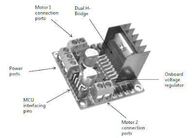
L298N dual H-bridge module with Arduino Uno
Figure 1 - An L298N dual H-bridge module with Arduino Uno

As shown above, there are two motor ports on either side of the L298N dual H-bridge module. A typical DC motor has two terminals. These terminals have to be connected with the motor connection ports as shown below.
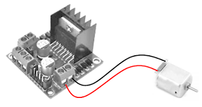
L298N Dual H-bridge with DC Motor and Arduino Uno
Figure 2 - L298N Dual H-bridge with DC Motor
Once the DC motor has been connected, the next steps is to make the power port connections. For this take a look at the next diagram.

L298N Dual H-bridge power pins with Arduino Uno
Figure 3 - L298N Dual H-bridge power pins with Arduino Uno

You will have to use either the 12V or the 5V power port for powering the module - don't use both together. The 12V port is to accept external power supply ranging from 5 - 35 volts - the module has an in-built 5 volt power supply unit to manage the power at the required level. Whereas the 5V port can be used for connecting to Arduino's 5V pin. The GND port should be used to tie the circuit with a common ground.

Parts Needed
Now that we know the bare minimum of the L298N dual H-bridge module, let us look at how to interface it with the Arduino Uno. As a first step, you will need the following parts for interfacing a L298N dual H-bridge motor driver module with the Arduino Uno:

  1. Arduino Uno R3 board
  2. USB-A to USB-B cable
  3. A half/full sized breadboard
  4. A L298N Dual H-Bridge motor driver module
  5. 2 normal/geared DC motors
  6. 4 x 1.5 volt AA alkaline batteries (you can use as per avalability)
  7. Battery holder case
  8. Some jumper wires

The Circuit
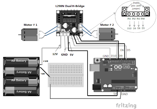
The breadboard setup for connecting the L298N dual H-bridge motor driver module with the Arduino Uno is shown below for reference.
Interfacing L298N Dual H-bridge with Arduino Uno
Figure 4 - Interfacing L298N Dual H-bridge with Arduino Uno

Build the circuit as depicted in the above breadboard diagram.

The Code
After the circuit has been built, use the following C sketch to control two DC motors via the L298N dual H-bridge motor driver module with the Arduino Uno.

// Motor # 1 (left side of diagram)
const int IN1 = 5;
const int IN2 = 6;

//Motor B (right side of diagram)
const int IN3  = 9;   // change to 10 if running robot wheels
const int IN4  = 10;  // change to 9 if running robot wheels

int speed = 190; // maximum 255, try lower value for non-geared motors

void setup()
{
    Serial.begin(9600);
    pinMode(IN1, OUTPUT);
    pinMode(IN2, OUTPUT);
    pinMode(IN3, OUTPUT);
    pinMode(IN4, OUTPUT);
}

void loop()
{
    char ch = 0;
    ch = Serial.read();

    if(ch == '1')
    {
      // turn Motor # 1 in one direction
      analogWrite(IN1, speed);
      analogWrite(IN2, 0);
      delay(500);
      analogWrite(IN1, 0);
    } 

    if(ch == '2')
    {
      // turn Motor # 1 in the other direction
      analogWrite(IN1, 0);
      analogWrite(IN2, speed);
      delay(500);
      analogWrite(IN2, 0);
    }

    if(ch == '3')
    {
      // turn Motor # 2 in one direction
      analogWrite(IN3, speed);
      analogWrite(IN4, 0);
      delay(500);
      analogWrite(IN3, 0);
    } 

    if(ch == '4')
    {
      // turn Motor # 2 in the other direction
      analogWrite(IN3, 0);
      analogWrite(IN4, speed);
      delay(500);
      analogWrite(IN4, 0);
    }

    if(ch == '5')
    {
      // turn both motors at once in one direction
      analogWrite(IN1, speed);
      analogWrite(IN2, 0);
      analogWrite(IN3, speed);
      analogWrite(IN4, 0);
      delay(500);
      analogWrite(IN1, 0);
      analogWrite(IN3, 0);
    }

    if(ch == '6')
    {
      // turn both motors at once in the other direction
      analogWrite(IN1, 0);
      analogWrite(IN2, speed);
      analogWrite(IN3, 0);
      analogWrite(IN4, speed);
      delay(500);
      analogWrite(IN2, 0);
      analogWrite(IN4, 0);
    }

    if(ch == '7')
    {
      // stop all motors, whether running or not running
      analogWrite(IN1, 0);
      analogWrite(IN2, 0);
      analogWrite(IN3, 0);
      analogWrite(IN4, 0);
    }
}

Interesting Applications
The L298N dual H-bridge motor driver module is frequently used for controlling motors in:
  1. Robotic vehicles and robot arms
  2. Lighting projects for controlling brightness
  3. Other innovative moving devices


If you liked this post, then your encouragement by performing a G+ and a share is most welcome and highly appreciated!

How to Use a Vibration Sensor or Shake Switch with Arduino Uno

In this post we will look at how to use a Vibration Sensor (also known as a Shake Switch) with the Arduino Uno. A common Vibration Sensor or Shake Switch used with the Arduino Uno has a technical model number known as SW-18015P or SW-18020P. We can also refer to them as SW-180 series Vibrator Sensors or Shake Switches.

Vibration Sensor or Shake Switch SW-18015P / SW-18020P
Figure 1 - Vibration Sensor or Shake Switch SW-18015P / SW-18020P


As shown above, a Vibration Sensor or Shake Switch looks like a cylindrical capacitor in shape.

The Vibration Sensor or Shake Switch
Inside the Vibration Sensor or Shake Switch there is a complex mechnical spring system wound around a central shaft. The following diagram based on the SW-180 vibration sensor series datasheet depicts the working principle of a vibration sensor.

Working principle of a Vibration sensor or Shake switch
Figure 2 - Working principle of a typical Vibration sensor or Shake switch


The internal spring mounted system moves when the sensor is acted uopn by external stimuli. The resultant movement within the Vibration Sensor or Shake switch results in a change in electrical voltage. This change in voltage can be measured by any micro-controller unit such as an Arduino Uno. Let us see how in the next section.

Parts Needed for Vibration Senbsor or Shake Switch with Arduino
You will need the following items for using a Vibration sensor or Shake switch with the Arduino Uno:
  1. Arduino Uno R3 board
  2. USB-A to USB-B cable
  3. A SW-180 series vibration sensor or shake switch
  4. A breadboard
  5. Some jumper wires

The Breadboard Circuit for Vibration Senbsor or Shake Switch
The breadboard setup for connecting the vibration sensor with the Arduino Uno is shown below for reference.

Using Vibration Sensor (Shake Switch) with Arduino Uno
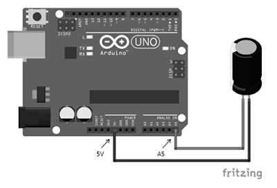
Figure 3 - Using Vibration Sensor (Shake Switch) with Arduino Uno


The connection are explained below for easy understanding.

  1. Connect one leg of the vibration sensor or Shake switch with Arduino Uno's analog pin A5
  2. Connect the other leg of the vibration sensor or Shake switch with Arduino Uno's 5V power supply pin

The Arduino C Sketch for Vibration Senbsor or Shake Switch
After the circuit has been built, use the following C sketch to interface the Vibration sensor or Shake switch with the Arduino Uno. The main point to note here is that when the sensor does not vibrate then the analog values will be greater than 1022. So in order to react to vibration pay attention to the logic writen in the if statement below.

// variable to store analog value read from the vibration sensor
int sensorReading;
int sensorPin = A5;

void setup()

{
   Serial.begin(9600);
}

void loop()

{
   sensorReading = analogRead(sensorPin);

   // normally when nothing is vibrating or shaking

   // the sensor values on the analog pin A5
   // will be between 1023 to 1024
   if (sensorReading < 1022)
   {
      Serial.print("Things started moving: ");
      Serial.println(sensorReading);
   }

   // check every 5 seconds
   delay(5000);
}

Interesting Applications of the Vibration Senbsor or Shake Switch
The SW-180 series vibrations switch can be utilized for building some interesting real worl applictaions such as:
  1. Anti-theft alarms
  2. Monitoring moving machinery/equipment
  3. Instruments / Toys
  4. Sport Equipments
Conclusion
This is how a SW-180 series vibration switch or shake switch is interfaced with an Arduino Uno.
This example has multiple fundamentals such as: reading analog I/O, fundamentals of interfacing with sensors, using sensor datasheets, using the Serial Monitor for sketch debugging and so on. These and many other things have been covered in detail in my book "Learn Arduino Prototyping in 10 Days".


If you liked this post, then your encouragement by performing a G+ and a share is most welcome and highly appreciated!