Showing posts with label Transceivers. Show all posts

How to use Bluetooth with Arduino

In this post, we will concentrate on how to use a Bluetooth module with the Arduino Uno. Bluetooth as we know is an electronic data exchange protocol over short distances. There are many different types of Bluetooth chips available in the market such as:
  • HC-04, HC-05 and HC-06
  • RN-41 and RN-42
  • AUBTM series chips

The multitude of chips are designed to fulfill different types of objectives. For example, range or the maximum distance over which communication is possible. In this post, we will use the HC-05 bluetooth chip which is a Class 2 bluetooth device. All Class 2 bluetooth devices should have an approximate range of 30 feet. In order to give you an idea of how you may put the bluetooth module to use, we will see how to blink a LED remotely by sending commands from a Windows Phone. The Arduino sketch used in this example is written in such a way that it will receive a number between 1 and 5, then depending on the number received from the phone, it will blink the LED that many number of times.

To start with let us inspect the HC-05 bluetooth chipset and try to understand the pins that are needed for making a connection with the Arduino Uno.

HC-05 Bluetooth
Figure 1 - HC-05 Bluetooth

There are 6 pins provided with the chip. Out of the 6 pins we will be using only 4 pins for the bare minimum interfacing.
  • Rx Pin (HC-05): This pin will be connected to Arduino Uno's Tx pin. However, we will shift Arduino's 5V to 3.3V using a votage divider. That is because the HC-05 module's Rx pin uses 3.3V.
  • Tx Pin (HC-05): Connect this pin to Arduino's Rx pin directly. Although HC-05's Tx pin works at 3.3V, it would still be sufficient for Arduino's RX pin which operates at 5V.
  • Gnd Pin (HC-05): This pin should be connected to Arduino's Gnd pin directly.
  • +5V (HC-05): This pin should be connected to Arduino's 5V pin. The current drawn by HC-05 should be less than 50mA, hence it should get the required current from Arduino's 5V pin.

For using the HC-05 with Arduino Uno, the first thing that we will have to do is to connect the chip with the Arduino Uno as explained above. You may follow the schematic diagram shown below for easy reference.

Using Bluetooth with Arduino
Figure 2 - Using Bluetooth with Arduino

Big Caution: DO NOT connect the Jumper wires to Arduino's Tx and Rx pins while loading the C sketch, to avoid loading the program to the Bluetooth device.

Good Practice: DO NOT connect anything to the Arduino while loading a program.

Once nothing is connected to the Arduino board, except the cable to your computer, load the following C sketch into your Arduino Uno for interfacing the LED with the Bluetooth module, as shown in the picture above.


Now connect the HC-05 module to the Arduino board and power on the Arduino board by connecting to your computer USB port.

On the other end, launch BT Terminal on your windows phone.
Connect to your HC-05.
In the Communication screen, send any number between 1 and 5 (as per your choice), as shown below.

Sending commands to HC-05 from Windows Phone
Figure 3 - Sending commands to HC-05 from Windows Phone


As soon as you send a number the on-board  LED on Arduino's Pin 13 will blink that many number of times.

That's it! You have established a basic bluetooth connected project.

Cheers!
KBRC

Post Data to ThingSpeak - Bad Request Problem Solved

In this post we will see the series of AT Commands that you may use from any serial terminal in order to successfully post data to ThingSpeak IoT Cloud.  Many people have reported of getting a Bad Request error returned when they tried to post data to the ThingSpeak server. It was indeed very tricky to figure this out a way to fix the Bad Request problem. Hence I am sharing this information as it was very troublesome to find all the required information in one place on the Internet.

Pre-Requisites

This post assumes that you already have an ESP8266 and a FTDI FT232RL USB to TTL Converter connected properly. You can refer for full connection details here.

The Data Logging Session

For sending data to ThingSpeak use the following series of AT commands from the Arduino Serial Monitor or from any other terminal of your choice. Set the Serial baud rate at 11500 and Both NL & CR. Then execute the following AT Commands.

AT

AT+CWLAP

AT+CWJAP="your-wifi-ssid","your-password"

AT+CIPSTART="TCP","184.106.153.149",80

AT+CIPSEND=60

GET /update?key=<your-channel-api-write-key>&field1=56\r\n        (from my Arduino IDE's Serial Monitor, I had to send this line 2 times...I don't know why yet)

AT+CWQAP

That is all! This should work fine. My Serial window snip is shown below for reference.

Post Data to ThingSpeak - Bad Request Problem Solved


Summary - The Trick

In the series of AT commands above notice the line "AT+CIPSEND=60", the number 60 here means the number of text characters (technically bytes) that will be sent in the request. It is referred to as the Data Length. Read below and see how to manipulate this Data Length setting in order to solve the Bad Request problem.

The request text is in the line "GET /update?key=<your-channel-api-write-key>&field1=56\r\n". In my case, the number of characters in this request text was 46 (including the last \r\n characters, you will have to count them as well). However, I specified 60 as the Data Length. This is the trick. You will have to mention the Data Length a little bit higher than the actual size of the Request Text length.

Cheers!
KBRC


If you liked this post, then your encouragement by performing a G+ and a share is most welcome and highly appreciated!

How to configure ESP8266 baud rate?

The ESP8266 baud rate must be changed to 9600 before connecting the ESP8266 with the Arduino Uno. The baud rate of your ESP8266 should be set to 9600, so that you can communicate with it via your Arduino IDE's Serial Monitor and also via the Software Serial while issuing AT commands for connecting from the C program to the internet.

By the way, setting up the FTDI FT232RL USB to TTL Converter is a separate topic altogether. You will have to set up the USB to TTL converter before you can use it to configure the ESP8266. You can read my detailed post of setting up the FTDI FT232RL USB to TTL Converter.

For changing the baud rate of the ESP8266 connect the chip with the USB to TTL converter as shown below. Also note that there is another way of using your Arduino Uno board to configure the ESP8266 chip, instead of the USB to TTL converter - in which case you do not need to use the USB to TTL FTDI chip - will write about it in a later post.

Caution: The FTDI FT232RL USB to TTL Converter I used had a jumper to select voltage level between 3.3V and 5V. Before connecting, I had switched the jumper to the 3.3V level. If your USB to TTL converter does not come with 3.3V, then you must use the voltage divider technique to obtain 3.3V on the Vcc and Tx pins.


Configure ESP8266 Baud Rate
Figure 1 - Configure ESP8266 baud rate using USB to TTL converter

Connect the ESP8266 to your PC, via the USB to TTL converter as explained below.
  • PC USB A --> USB to TTL FTDI
  • USB-to-TTL FTDI TX --> ESP8266 RXD (via voltage divider, if 3.3V mode not available)
  • USB-to-TTL FTDI RX --> ESP8266 TX
  • USB-to-TTL FTDI GND --> ESP8266 GND
  • USB-to-TTL FTDI VCC --> ESP8266 VCC and CH_PD (via voltage divider, if 3.3V mode not available)
Next in order to configure ESP8266 chip's baud rate, fire up the Arduino IDE and browse to the Serial Monitor. In the serial monitor, you will have to perform some trial and error to find out the existing baud rate of your ESP8266 chip. Set the line ending to "Both NL & CR". Then start with the highest rate of 115200, then type the command AT in the Serial Monitor and send it to the ESP8266 chip. If the selected baud rate matches the you will see OK displayed as a reply in the Serial Monitor window. Repeat this process of changing the baud rate from the Serial Monitor and pinging the ESP8266 chip with the AT command, until you receive OK as a reply. In my case (shown below) the factory set baud rate was 115200.

Using ESP8266 with Arduino Uno
Figure 2 - Finding Factory Set Baud Rate of ESP8266

If the baud rate matches with 9600, then no further action is required and you may proceed with setting up the ESP8266 with the Arduino Uno. If the matching baud rate is something other than 9600, then you will have to change the baud rate of your ESP8266 chip by issuing the following AT command (AT+CIOBAUD=9600) in the Serial Monitor window.

Using ESP8266 with Arduino Uno
Figure 3 - Change Baud Rate of ESP8266

This is how you configure the baud rate of your ESP8266 chip! Just to be sure that the baud rate was indeed changed, issue the command AT in the Arduino Serial window. You should receive OK as a reply if everything went successfully so far. Otherwise repeat the AT command to change the baud rate.

Using ESP8266 with Arduino Uno

Using the ESP8266 with Arduino Uno is one of the fundamental methods of connecting edge devices (aka. "things") to the internet. We will use a chip called the ESP8266 (this is a Wifi capable chip with a built-in antenna) with the Arduino Uno, for logging messages to an IoT Cloud platform. For the purpose of this demonstration we will use a free IoT platform called ThingSpeak. However, you are free to choose from AWS, Azure, Dweet, Particle, your own "bespoke" stuff or many more out there. I chose ThingSpeak because it was absolutely free (no Credit Card needed for signing up). However, the limitation of the ThingSpeak IoT platform, atleast the free stuff I am using here, is of accepting ONLY ONE incoming message per 15 seconds - so in one minute you will be able to send a maximum of 4 messages only.

A Word Of Caution

This is an advanced setup for connecting the ESP8266 with the Arduino Uno, not recommended without a good understanding first - one small mistake and the ESP8266 chip (3.3V) might get fried (if unfortunate). Using the ESP8266 with the Arduino (5V) is fundamentally different from using any other 5V compatible component, because of the multiple voltage levels involved in this circuit setup.

Dos & Don'ts

 While setting up the ESP8266 with Arduino Uno, always use a separate power source for connecting the ESP8266 to the Arduino Uno. Do not use the 3.3V power supply from Arduino. The ESP8266 operates on 3.3V DC, whereas the Arduino Uno operates on 5V DC. The ESP8266 requires currents much greater (120 - 170 mA while transmitting wireless packets - refer Page 19 of the manufacturer's datasheet) than what can be supplied by an Arduino Uno 3.3V pin (~50mA - refer this for details). Hence you will have to grasp the following fundamentals.
  • Using Multiple Power Sources in the same circuit - Powering the Arduino board from a 5 V power source and ESP8266 from a 3.3V power source.
  • Common Grounding - How to give the Arduino board and the ESP8266 chip a common GROUND, even though they are powered from two different power sources?
  • Voltage Division - How to reduce 5V to 3.3V using the Voltage Division Technique for connecting the Arduino Tx Pin (5V) to ESP8266 RXD Pin (3.3V)?
In the following sections we will see how to actually hook up the ESP8266 with the Arduino Uno, in the wiring diagram below.

Hardware Needed
  • Arduino UNO
  • USB A to B cable (for programming the Arduino UNO)
  • Breadboard
  • Jumper Wires (M2M, M2F and F2F)
  • ESP8266
  • FT232RL USB to TTL Converter (for configuring the ESP8266)
  • USB A to mini B cable (for connecting the FT232RL USB to TTL converter)
  • DC/DC Step-Down 3.3V Converter (alternately you may use an AMS1117 3.3V regulator and some capacitors, but it is a bit advanced)
  • AAA Battery Holder (for 4 x 1.5V batteries)
  • 4 Pcs. of 1.5V Batteries
  • Soldering Kit (you may need this to join the power supply wires to some header pins)
  • Multimeter (to check the output of the 3.3V voltage converter really 3.3V or not...I am a bit paranoid while working with off the shelf electronic components)

Software Needed
  • Arduino IDE
  • IoT Cloud Channel
Here onwards, we will proceed gradually, one step at a time, for connecting the ESP8266 with Arduino Uno. Basically we will have to take the following steps in order to push data into the IoT cloud platform:
  • Configure the ESP8266
  • Wire the ESP to the Arduino
  • Setup a Channel (for each edge device) in the IoT Cloud
  • Write a C program for using the ESP8266 from the Arduino board

Configuring the ESP8266

This is a very important step in this setup and must be performed before connecting the ESP8266 with the Arduino Uno. The baud rate of your ESP8266 should be set to 9600, so that you can communicate with it via your Arduino IDE's Serial Monitor and also via the Software Serial while issuing AT commands for connecting from the C program to the internet. You can refer to the steps to configure the ESP8266 hrer.

Wiring the ESP8266 with the Arduino UNO

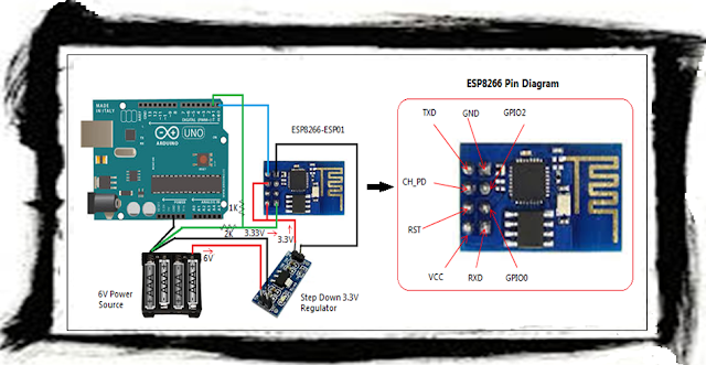
         While wiring the ESP8266 with the Arduino Uno, exercise caution while connecting this setup. Make sure that any voltage into the ESP8266 chip is around 3.3 volts. Use a multimeter to double check the voltage. The remaining setup shown below is self-explanatory for wiring the ESP8266 with the Arduino Uno.
ESP8266 with Arduino UNO
Figure 4 - Wiring of ESP8266 with Arduino Uno 

Wire the ESP8266 to the Arduino UNO as described below:

  • Arduino TX --> ESP RXD (using voltage division method) and then into Common GND - the GREEN line shown in the picture
  • ESP TXD --> Arduino RX (no voltage shifting needed) - the BLUE line shown in the picture
  • Arduino GND --> Common GND (-ve Terminal of power source)
  • ESP GND --> 3.3V Step-Down Regulator  GND
  • ESP VCC & CH_PD --> 3.3V Step-Down Regulator VOUT
  • 3.3V Step-Down Regulator VIN --> +ve Terminal of power source
  • 3.3V Step-Down Regulator --> -ve Terminal of power source

Setting up a ThingSpeak Channel

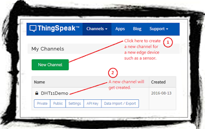
          After connecting the ESP8266 with Arduino Uno, the next thing that you will have to do is to create an account in an IoT Cloud platform, so that you may use it to log the data from the edge device (node MCU as they call it sometimes) or sensor, using the ESP8266 with Arduino Uno. For this purpose, I will be using www.ThingSpeak.com to demonstrate how the setup a channel to receive data from a device. The term "channel" in the context of an IoT cloud simply means an endpoint (an exposed web service and/or web service method) to receive data from the sensor. Hence for each device you will have to create a corresponding channel. I will write a dedicate post on setting up and configuring the ThingSpeak account and channel, at a later time. For now I will provide the minimum information needed to log data from a sensor to the cloud. After creating your account, create a New Channel and then configure it by following the on screen instructions. Once the new channel is created it will appear in your account's My Channels dashboard (Channels > My Channels), as shown below.
ESP8266 with Arduino UNO
Figure 5 - ThingSpeak Channel for receiving data from ESP8266 with Arduino Uno

          Next, step is to find out the how to log and read data to and from this channel. ThingSpeak provides several ways to integration data, such as:
  • Simple GET and PUT using URLs from a browser
  • Simple GET and PUT from JavaScript or any other code
  • It also provides a library (the C header file - ThingSpeak.h) for use with an Arduino Uno
          For a quick flavour of how to log and read data consider the following simple examples based on hitting URLs from your browser window. Remember to replace your api_key in appropriate places below. You will be alloted an api_key once you create a channel in ThingSpeak - it is basically a public key that secures your channel from accepting data from an unintended source.

Logging Data:
https://api.thingspeak.com/update.json?api_key=<your-write-api-key>&field1=58

Reading Data (this URL format will return the last logged data row):
https://api.thingspeak.com/channels/<your-channel-id>/feeds.json?key=<replace-with-your-api-key>&results=1


The C Program for Posting Data to ThingSpeak

Use the following C program for using the ESP8266 with Arduino Uno, to read the sensor data and then log it to the ThingSpeak IoT cloud. In this example, we are not going to use either the ThingSpeak API or the ESP8266 API for Arduino. We will use only AT commands.


Conclusion

          In conclusion, using the ESP8266 with the Arduino Uno will pose some practical challenges for the IoT prototypist. Specially, using multi-voltage devices in the same circuit. I hope you find this post useful. Do leave your comments and experiences below. I would love to hear from you!

Cheers!
KBRC